ESP32 Quirks (Latching Pins, Auto-Programming Mode, USB-C, etc.)
Sometimes there’s just some weird bit of knowledge you need to know before working with a specific chip/microcontroller that you wouldn’t have guessed. Here’s my list from working with the ESP32 on my latest handheld game engine project.
Summary:
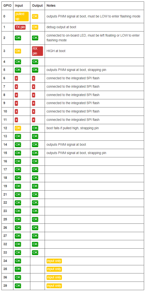
For GPIO, start by only using pins: GPIO 4, 13, 16 – 33. If you need more pins, read up on the quirks of each pin. Some need to be pulled high, low, or left floating on boot, some output stuff on boot, some are reserved for internal SPI Flash, and some are input only.
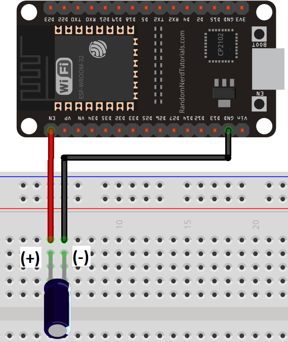
Cheap knockoffs don’t have a necessary capacitor that enables the board to automatically go into auto-programming mode (without pressed any buttons). Solder a 10uF capacitor from the EN pin to ground (long end of the cap soldered to EN, short end to GND).
Many Pins Can’t be Used
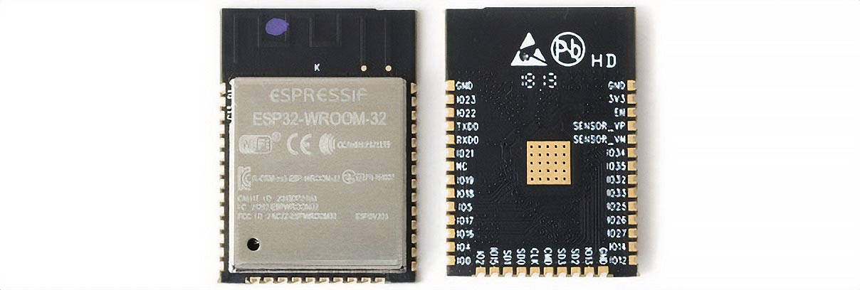
The ESP32 has 48 pins, 40 of which are labeled as general purpose input/output (GPIO) pins. However, there are only 14 truly general purpose input/output pins. These 14 don’t have an special requirements or internal uses by the microcontroller. You can use more of the other pins, but you have to keep in mind their quirks. More information about the ESP32 pins can be found on this article.
Strapping Pins (Boot Related)
These pins must be set correctly at boot and are used to put the chip into a specific boot mode/programming mode, to hide debug logs, etc. These include:
- GPIO 0, 2, 4, 5, 12, and 15.
This one is annoying because the Espressif official documentation says to use GPIO 2 for the SDIO interface, yet, the interface requires pulling up GPIO 2. Somehow it’s fine if I use a high enough pullup resistor like 47k, but it fails to program if you use a 4.7k resistor. Go figure.
Pins that Output on Boot
Some pins are connected to 3.3v on boot (called going HIGH) or they output a signal called PWM on boot. If you connect a component to these pins, be aware of this behavior on boot. You wouldn’t want to unintentionally start a transaction with a peripheral or mess up the boot sequence of another component.
- Pins that go HIGH: GPIO 1, 3, 5, 6, 7, 8, 9, 10, 11, 14, and 15
- Pins that output PWM: GPIO 0, 5, 14, 15
Auto-Programming Mode
All the cheap knockoff ESP32 dev kit boards that I’ve bought have all been unable to auto-program. Some people online figured it needed a capacitor to make the reset signal last longer and to properly put it into the right programming mode. Adding a medium sized 10uF capacitor across EN and ground solved the issue for me. Read more about programming the ESP32 and this fix from this article.
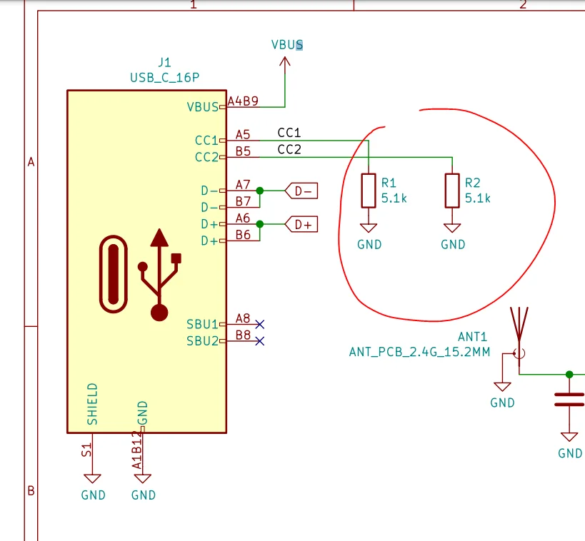
USB-C Protocol
For my project, I wanted to use a USB-C charging circuit with a TP4056 Li-ion charging circuit. However, many cheap USB-C circuits are missing two resistors that tell the charger to provide 5v. The crazy thing is some cheap knockoff chargers automatically output 5v! So this problem was really weird since my more expensive USB-C chargers (e.g. Lenovo laptop charger or Samsung phone chargers) didn’t work, but the cheap chargers did.
If you have a USB-C circuit and the cable/charger is outputting nothing, check to make sure the circuit has two 5.1k resistors grounding the CC1 and CC2 lines. This is part of the protocol to signal that the circuit wants 5v at a certain amperage.
Related posts
![]()
SimmiMega: Micro-Game Making Machine (Dev Log #2)
After the last dev log, I was trying to wire the resistive touchscreen wires directly to some of the unused analog pins left on the ESP-32, but I realized I didn’t have enough pins left. Some of the pins on the ESP-32 were input only, and some didn’t support analog reads. Instead, I ordered some…
![]()
16 Ways to Reduce Arduino Compile Size
There are many ways to reduce the compile size of a programming project. Varying in complexity and cost, here are 16 of the ways I’ve used to reduce the size of my projects.